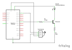
To assemble the electronics, follow the circuit diagram available here (pdf). Although the schematic does not make it clear, the Raspberry Pi has multiple grounds, and you can use this to your advantage. We connected the TSOP and LED loops to two different grounds (the TSOP to board pin 14, the LED to board pin 6). This allowed us to use only one ribbon cable to connect all of the components.